Methods of venting plumbing fixtures and traps in the 2021 International Plumbing Code
 The International Code Council is proud to distribute a helpful tool — Methods of Venting Plumbing Fixtures and Traps in the 2021 International Plumbing Code: Installation, Flexibility and Opportunity for Savings — to help expand your knowledge of the International Plumbing Code (IPC). The various approaches to venting that are permitted in the 2021 IPC are described in this handy reference tool authored by Lee Clifton, senior director of PMG resources at the Code Council. You will find that these venting provisions offer the installer and designer different paths to achieving an adequately vented system, which could result in cost savings along with ease of installation in different types of construction.
Chapter 9 of the IPC describes a variety of methods to vent plumbing fixtures and traps. The methods have been laboratory tested to determine sizing and installation requirements that provide proper venting to a drainage system. The venting methods have also been field-tested, establishing a long history of satisfactory service.
In this last of a four-part series of articles, we look at the three remaining venting methods in the IPC: circuit venting, combination waste and vent systems, and single stack vent systems. Circuit venting was included in Dr. Roy B. Hunter’s research and reported in BMS 66 (a methodology for determining necessary pipe sizing by estimating maximum demand on the delivery and drainage systems). The plumbing community has long recognized this venting method and it is included in the ASPE Data Book: A Plumbing Engineer’s Guide to System Design and Specifications. The combination waste and vent system is based on the same premise as the circuit-vented system. The performance of the combination waste and vent system was verified in tests conducted at the Stevens Institute of Technology. The Single Stack Vent System was introduced into the IPC in the 2012 edition and is based on a drainage stack system in the city of Philadelphia (Pennsylvania) Plumbing Code, which has been used successfully in many multi-story and high-rise buildings for more than 100 years.
Circuit venting
The IPC has a variety of methods that can be used to vent plumbing fixtures and traps. Circuit venting is one of these methods and it has been laboratory and field-tested, establishing a long history of satisfactory service. Extensive research into the performance of circuit vented systems was conducted at the State University of Iowa. The research concluded that the single vent for the eight fixtures provided the necessary protection of the trap seal. Circuit venting was included in Roy B. Hunter’s research at the National Bureau of Standards and reported in BMS 66.
The venting method has long been recognized by the plumbing community and is included in the American Society of Plumbing Engineers Data Book. The principle of circuit venting is that the flow of drainage never exceeds a half-full flow condition. The air for venting the fixtures circulates in the top half of the horizontal branch drain pipe. The flow velocity in the horizontal branch is slow and non-turbulent, thereby preventing pressure differentials from affecting the connecting fixtures. The circuit-vented fixtures must connect to the circuit-vented branch in the horizontal plane to limit the amount of turbulence created by fixture discharge.
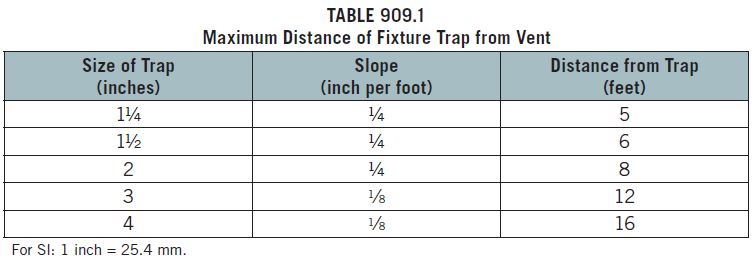
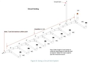
The Circuit Venting method is similar to wet venting except that it allows you to combine a total of eight fixtures on a single floor that are not limited to the two bathroom groups. It might be easier to explain by examining how circuit venting differs from wet venting. The fixture drains shall connect horizontally to the horizontal branch being circuit vented. Again, the fixture drains are limited in length to those shown in Table 909.1. Because circuit venting is only to be used on horizontal applications as opposed to wet venting, which can be both horizontal and vertical installations, the maximum slope for a circuit vent is 1 unit in 12 units horizontally, or 8-percent slope. The entire length of the circuit vent portion of the horizontal branch shall be sized for the total drainage discharge to the branch (see Figure 9). There is not a unique sizing table for circuit venting as there is for wet venting or common venting.
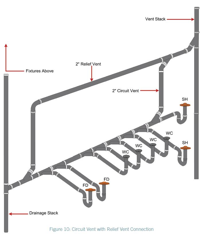
The circuit vent connection must be located between the two uppermost fixture drains and shall connect to the horizontal branch. It cannot serve as a drain for other fixtures—it is truly a dry vent. Where a circuit vent consists of four or more water closets and discharges into a drainage stack that also receives the discharge of upper horizontal branches, a relief vent shall be connected to the horizontal branch ahead of the connection to the drainage stack and after the most downstream fixture drain of the circuit vent (see Figure 10).
Additional fixture drains may be connected with the circuit-vented branch, but they need to be vented by means other than the circuit vent, and the fixture unit values would be added to the total fixture unit discharge into the horizontal branch. Such fixtures must also be located on the same floor as the circuit vent to which they connect. Where the relief vent receives the discharge of other fixtures, the maximum discharge allowed is 4 drainage fixture units.
Combination waste and vent system
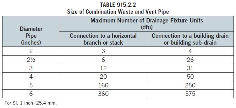
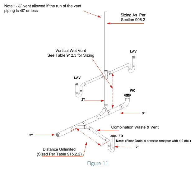
This system is based on the same premise as the circuit-vented system. Most plumbing codes place arbitrary restrictions on combination drain (waste) and vent systems because the system appears too good to be true. The performance of the combination waste and vent system was verified in tests conducted at the Stevens Institute of Technology. If sized according to Table 915.2.2 in the IPC, the study concluded that the distance from a trap does not have to be limited in length. This is a horizontal wet vent system limited to floor drains, standpipes, sinks and lavatories for the purpose of venting, except that a vertical riser, not to exceed 8 feet in length, may be used to connect a fixture drain to the horizontal combination drain and vent system. Again, the idea here is that the top half of the horizontal drain acts as a vent. As long as both the horizontal drain and vent system and the maximum 8-foot riser to a fixture drain are sized in accordance with Table 915.2.2, the flow of free air will be sufficient for the propped design.
Of course, to get that free flow of air, a vent to the atmosphere must be provided. The vent, which must be sized for the total drainage fixture load of the combination drain and vent system per Section 906.2, can be located anywhere on the system and must rise vertically not less than 6 inches (152 mm) above the flood level rim of the highest fixture being vented before offsetting horizontally. This type of system is unique in that a branch that is already vented can accept a fixture drain under this combination waste and vent method (see Figure 11). Remember, too, that this type of venting procedure is dependent on adequate sizing and maintaining a horizontal installation. For this reason, the horizontal portion must not exceed a slope of one-half unit vertical in 12 units horizontal, or 4-percent slope. The horizontal length of a combination waste and vent system shall be unlimited.
The IPC continues to emphasize both prescriptive- and performance-related provisions. Next we are going to discuss the Single Stack Vent System. This proven venting system method now compliments the most extensive collection of venting options in the world.
Single stack vent system
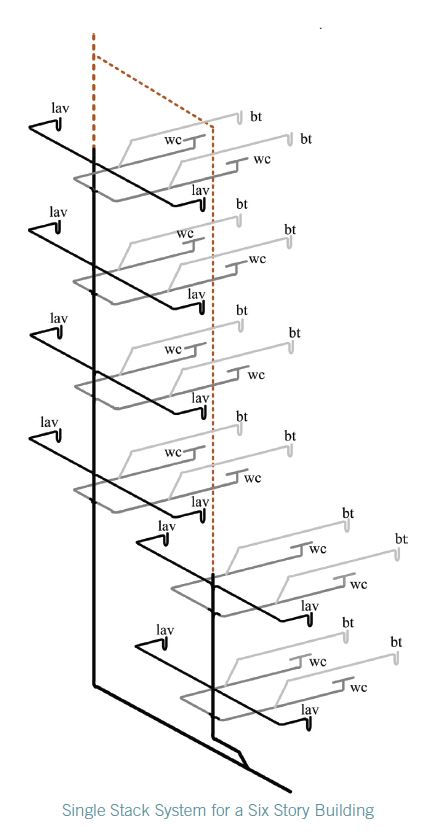 The Single Stack Vent System was introduced into the IPC in the 2012 Edition and is based on a drainage stack system in the City of Philadelphia (Pennsylvania) Plumbing Code which has been used successfully in many multi-story and high-rise buildings for over 100 years. The Philadelphia System is described in Volume 2, Chapter 3 of the American Society of Plumbing Engineers (ASPE) Data Book. The Philadelphia or ‘one pipe’ system refers to the use of one drainage stack instead of having separate drainage and vent stacks The Philadelphia system successfully utilizes “S” traps for fixture traps located above the floor and within a specified distance from the stack. However, because the IPC prohibits the use of S traps, the Single Stack Vent System in the IPC utilizes an oversized vertical pipe from its connection at the end of the fixture trap’s fixture drain (also known by some tradesmen as a ‘trap arm’) to the horizontal drainage piping of the system. This is the same concept utilized in combination waste and vent systems for fixtures that are located above the floor. The oversized vertical pipe eliminates any possibility of siphoning of a fixture trap as the waste volume entering the vertical pipe could not possibly block the venting air space in the vertical pipe.
In a Single Stack Vent System the drainage stack serves as both a single-stack drainage and vent system. The drainage stack and branch piping are considered as vents for the drainage system as a whole. Pipe sizing in a single stack drainage system is larger than in a conventional one, however a significant cost saving is achieved by the reduction of the vent piping needed. This venting system serves as a viable alternative to the more traditional systems that are being used. The length of trap arms is limited and the vertical drop from the fixtures is oversized also. Fixture connections that do not meet the requirement for a single stack system must be conventionally vented. The length of the trap arm is limited to reduce any suction buildup, and the stack is oversized to limit the internal air pressure and vacuum build up. Stacks greater than two branch intervals in height are prohibited from receiving the discharge of horizontal branches on the lower two floors. The separate stack serving the lower two floors, is required to connect to the building drain at a distance of not less than 10 pipe diameters downstream from the base of the connection of the single stack vented system. This proven method has been laboratory tested to determine sizing and installation requirements that provide proper venting to the drainage system.
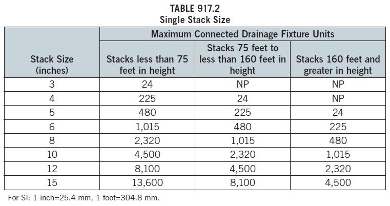
The size of a single stack drainage stack is based upon the height and the total number of dfu connected to the stack. Table 917.2 provides the stack dfu limitations according to stack height. The height of the stack is from the connection to the building drain to the uppermost drainage connection to the stack. Drainage stacks must be the same size from the base to the termination of the stack to the outdoors. The requirement for the stack vent to be the same size as the drainage stack allows the stack vent to be of any length on its path to its termination point outdoors.
For a 3-inch (76 mm) stack, there is a limitation of two water closets on the stack. This limits the amount of solids in this small diameter stack so that airflow is not impeded.
Table 917.2 is used simply by identifying the column that includes the height of the stack and then reading down that column to identify the row that has a dfu value that meets or exceeds the total dfu load on the stack. Once the row is identified, the user will find the stack size required from the first left-hand column. For example, the total load on the stack is 1000 dfu and the height of the stack is 150 feet (45,720 mm), the third column from the left is chosen and the row for an 8-inch (203 mm) stack size is identified. The “NP” in the table means not possible.
The sizing of the horizontal branches that connect to the stack is according to Table 710.1(2). Only the first and second columns of this table are to be used for sizing. The remaining columns of the table covering stacks have no relationship to this section. For example, if a horizontal branch is required to carry 170 dfu, then a 5-inch (127 mm) horizontal branch is required.
A 3-inch (76 mm) horizontal branch with a water closet located within 18 inches (457 mm) horizontal developed length of the stack has special limitations. If a water closet is located within 18 inches (457 mm) of the horizontal developed length of the stack and the connection is not made with a sanitary tee, then the only fixture that can be served by that horizontal branch is that water closet. If the connection to the stack of a 3-inch (76 mm) horizontal branch serving a single water closet is made using a sanitary tee, then one fixture having a 1½-inch drain can also be connected to the 3-inch (76 mm) horizontal branch.
Where a horizontal branch connects to the stack through a wye connection and the branch carries the discharge of one or more water closets, the water closet must be not more than 4 feet (1219 mm) in horizontal developed length from the stack. If the connection at the stack is made with a sanitary tee, the distance limitation is extended to 8 feet (2438 mm) in horizontal developed length.
Section 917.5 specifies the minimum sizes for the vertical portions of the fixture drains (other than water closets), that are connected to horizontal branches. Vertical sections of the fixture drains are required for fixtures such as lavatories, wall hung urinals, and standard pipes with traps above the horizontal branch. The minimum size for any vertical section of fixture drain is 2 inches (51 mm), except where standpipes and water-supplied urinals have vertical sections of fixture drains, then the vertical section must be 3 inches (76 mm). If the vertical sections of the fixture drains cannot be of these minimum sizes, then the fixture drains must be vented by a method other than the single stack method.
The height of the vertical section must not be greater than 4 feet (1219 mm). If the height is greater than 4 feet (1219 mm), then the fixture requires venting by a method other than the single stack method. In most situations, fixtures will not be greater than 4 feet (1219 mm) above the horizontal branch so additional venting methods are typically not required.
In arrangements where a horizontal branch carries the discharge of two or more water closets and the horizontal developed length of other fixtures discharging to the horizontal branch exceeds the limitations of Section 917.4, then those fixtures (other than water closets) located beyond the developed length limitation require venting by a method other than the single stack method. Section 917.6 indicates all of the types of venting that can be used for this purpose.
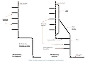
Section 917.7 addresses horizontal offsets in a single stack vent system. Where horizontal branches or fixture drains connect below a horizontal offset of a stack, the offset requires venting in accordance with Section 907.
Fixture drain connections to the stack must be made in the area of the stack that is 2 feet (610 mm) above or below the horizontal offset. Where there are no fixtures below the horizontal offset, the offset does not require venting. The total number of dfu coming from the stack is used to size the building drain and building sewer in accordance with Table 710.1(1).
Many experienced plumbers and Inspectors will agree that the venting requirements of a plumbing system are usually the most difficult to comprehend. The IPC contains more types of venting methods than are shown in other plumbing codes. As you continue to examine various methodologies, you will begin to see how they provide viable alternatives to “typical” venting options.
The full brochure — Methods of Venting Plumbing Fixtures and Traps in the 2021 International Plumbing Code: Installation, Flexibility and Opportunity for Savings — is available online.
For more information on the Code Council’s PMG Program and resources, contact Jim Cika, director of PMG Resources.
