
CodeNotes: Water Heater Safety in the I-Codes
This CodeNotes resource provides tips on how to properly install and maintain water heaters in your home.
This edition of CodeNotes — Water Heater Safety in the I-Codes® — is based on Section 504.6 of the 2021 International Plumbing Code® and Section P2804.6.1 of the 2021 International Residential Code®
Introduction

The water heater installed in a home can be a ticking time bomb if not installed correctly or maintained properly. A water heater temperature and pressure relief valve is an important safety device for a water heater as well as the water distribution system to which it is connected. If the water heater is operating properly, the pressure in the water distribution system is no greater than is required by the code, and the relief valve is in proper operating condition, then there should not be any water discharge from the relief valve. Any water discharge from the relief valve is an indication of a water distribution system problem, a water heater problem or that the relief valve is malfunctioning.
There are other important items associated with the relief valve. These items are mentioned in Section 504.6 of the IPC and Section P2804.6.1 of the IRC. These sections address the requirements of discharge piping serving a pressure relief valve, temperature relief valve or combination temperature and pressure relief valve. Because the discharge piping from these safety devices that serve water heaters are an extension of the potable water distribution system, the outlet of the discharge pipe must be treated as a potable water supply system outlet.
Item 1 states the discharge piping not be directly connected to the drainage system. Although an air gap is already required for the protection of the potable water supply in Section 608.16.1, a plumber or other authorized installer might not realize that the termination point of the relief valve discharge pipe shall also provide for an air gap.
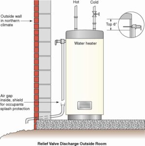
Item 2 requires the discharge to terminate through an air gap located in the same room as the water heater. (See Figure 1)
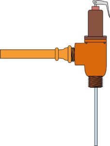
Item 3 requires the discharge piping not be smaller than the diameter of the outlet of the valve served and must discharge full size to the air gap. (See Figure 2)
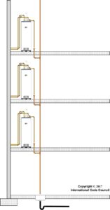
Item 4 requires the discharge piping serve only a single relief device and that it shall not connect to piping serving any other relief device or equipment. Figure 3 illustrates an approved means of connecting the discharge from multiple water heater relief valves. The code is silent as to the size or shape of the waste receptors and the gravity drain line size for capturing and conveying the discharge water from relief valves.
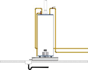
Item 5 requires that the discharge piping serving relief valves, discharge to the floor, to the pan serving the water heater or storage tank, to a waste receptor or to the outdoors. Figure 4 illustrates the discharge terminating to the pan.
Item 6 requires the discharge piping to discharge in a manner that does not cause personal injury or structural damage. A good example of locations that are not suitable for the termination of relief valve drain lines are shower floors, laundry trays, kitchen sinks, and bathtubs. Anyone that would be using these fixtures could be subject to injury by hot water and steam that could come from the pipes.
Item 7 requires the discharge to terminate to a point that is readily observable by the building occupants. It is important that the occupant be aware of the discharging relief valve or valves as soon as possible to limit the amount of discharge that may possibly cause damage or injury.
Items 8 and 9 require the relief valve discharge line to not be trapped and must drain by gravity without sags in the piping. Retained water in these trapped areas or piping sags might cause a buildup of scale or corrosion over time, or possibly freeze if the piping is located in an area that is subject to freezing. Both situations have the potential to create a blockage to any discharge that might come from a relief valve which would create a dangerous condition.
Item 10 requires the relief valve to terminate no more than 6 inches (152mm) above the floor surface, a waste receptor or floor drain in order to prevent hot water discharge from being directed onto a building occupant that may be nearby. Obviously, for termination points to the floor, the floor must be a suitable location for water discharge or a floor drain or waste receptor must be provided to capture and direct discharges from the pipe. See figure 5 for example of approved and unapproved termination.
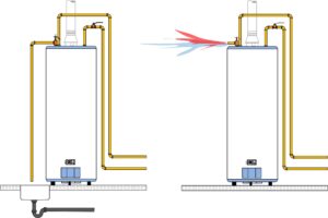
Item 11 requires the discharge piping have no threaded connection at the end of such piping. This would make it easy for someone to screw on a cap or valve to stop the dripping water from the pipe. What might be perceived as an easy repair by the handyperson could create a dangerous situation that could result in severe damage of the building and injury or death of the occupants. (See Figure 6)
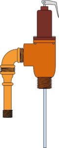
Item 12 prohibits discharge pipes from having valves or tees installed. The valve and tee fittings are obviously prohibited as the valve can be closed creating a dangerous situation and the tee fitting could allow connections of piping from other sources. (See Figure 7)
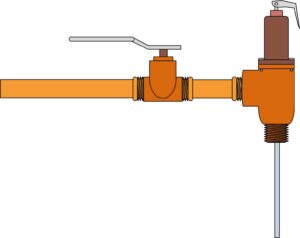
Item 13 requires that discharge piping be constructed of materials listed in Section 605.4 or materials tested, rated and approved for such use as in accordance with ASME A112.4.1. Piping material that comes in contact with potable water is required to conform to NSF 61. Pipe installed in a water distribution system must be capable of withstanding the working pressure of the system at the maximum hot water temperature that could be present in the system. The discharge piping shall have a pressure rating of not less than 100 psi (690 kPa) at 180°F (82°C). The reason the maximum working pressure for the pipe is set at 100 psi (690 kPa) is because of the possibility of pressure surges in a water distribution system.
Item 14 requires that the discharge piping serving a pressure relief valve be one nominal size larger than the size of the relief valve outlet, where the relief valve discharge piping is installed with insert fittings. The outlet end of such tubing shall be fastened in place. Figure 8 illustrates the reduction in the inside diameter of the pipe that would result in a restricted flow during a “full trip” event of the relief valve.
To summarize, the installation requirements of discharge piping serving a pressure relief valve, temperature relief valve or combination temperature and pressure relief valve mentioned in Section P2804.6.1 of the IRC and Section 504.6 of the IPC are extremely important. If not installed as required by this code could result in contamination of the potable water supply system and or create a very dangerous situation that could result in an explosion.
To order the 2021 IPC or IRC, Commentaries or other support references, visit here.


