CodeNotes: Fire, Smoke, and Combination Fire/Smoke Damper Fundamentals in the I-Codes
This CodesNotes resources provides fundamental information on the proper application of fire, smoke and combination dampers and their performance in the life/safety system.
This edition of CodeNotes — Fire, Smoke, and Combination Fire/Smoke Damper Fundamentals in the I-Codes — is based on the 2021 International Building Code® and the 2021 International Mechanical Code®.
Damper Requirements
The International Building Code (IBC) Section 717 and the International Mechanical Code (IMC) Section 607 address both ducted and unducted (air transfer openings) systems and provides the details for locations where the openings are required to be protected. These sections of the IBC and the IMC address items such as damper test standards and types of dampers, actuation of the damper, access requirements and where the various dampers are required.
Damper Types
There are five general types of dampers which are used in the various configurations permitted by the IBC and IMC. Each of these dampers has a very specific application and is tested to show compliance with the intended application. The five general types of dampers are Ceiling Radiation Damper, Combination Fire/Smoke Damper, Corridor Damper, Fire Damper, and Smoke Damper.
Definitions
Ceiling Radiation Damper. A listed device installed in a ceiling membrane of a fire-resistance-rated floor/ ceiling or roof/ceiling assembly to limit automatically the radiative heat transfer through an air inlet/outlet opening. Ceiling radiation dampers include air terminal units, ceiling dampers and ceiling air diffusers. Ceiling radiation dampers are classified for use in either static systems that will automatically shut down in the event of a fire, or in dynamic systems that continue to operate during a fire. A dynamic ceiling radiation damper is tested and rated for closure under elevated temperature airflow.

Combination Fire/Smoke Damper. A listed device installed in ducts and air transfer openings designed to close automatically upon the detection of heat and resist the passage of flame and smoke. The device is installed to operate automatically, be controlled by a smoke detection system, and where required, is capable of being positioned from a fire command center.

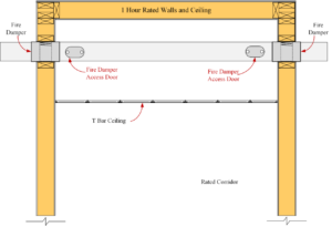
Corridor Damper. A listed device intended for use where air ducts penetrate or terminate at horizontal openings in the ceilings of fire-resistance-rated corridors, where the corridor ceiling is permitted to be constructed as required for the corridor walls.
Fire Dampers. A listed device installed in ducts and air transfer openings designed to close automatically upon detection of heat and to restrict the passage of flame. Fire dampers are classified for use in either static systems that will automatically shut down in the event of a fire, or in dynamic systems that continue to operate during a fire. A dynamic fire damper is tested and rated for closure under elevated temperature airflow.

Smoke Damper. A listed device installed in ducts and air transfer openings designed to resist the passage of smoke. The device is installed to operate automatically, controlled by a smoke detection system, and where required, is capable of being positioned from a fire command center.
In this CodeNote™ we will discuss the basic requirements of Fire, Smoke, and Combination Fire/Smoke Dampers.

Fire Dampers
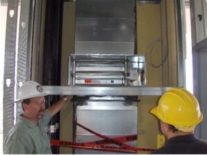
Fire Dampers are crucial passive fire protection products and are designed to close automatically when heat is detected and are used to restrict the spread of fire where ducts and air transfer openings penetrate fire walls, fire barriers, fire partitions, horizontal assemblies, shaft enclosures and occasionally exterior walls. Section 717.5 of the IBC and Section 607.5 of the IMC provides a listing of the various locations where dampers are required for walls and specifies the type of damper that is required at each specific installation. Section 717.6 of the IBC and Section 607.6 of the IMC do the same thing by specifying the location and type of dampers required to be installed with horizontal assemblies.

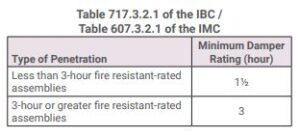
Fire dampers are classified in two types, static fire dampers and dynamic fire dampers. Fire dampers for use in either static systems or dynamic systems must have the minimum rating specified in Table 717.3.2.1 of the IBC and Table 607.3.2.1 of the IMC. Fire dampers for use in static systems, as their name implies, are only to be used in duct systems or penetrations where the HVAC system is automatically shut down in the event of a fire.

Fire dampers for use in dynamic systems are required at locations where the HVAC system continues to operate during a fire incident, and as such, the dampers must be capable of closing against the air velocity and pressure produced by the system fan. Dynamic dampers must be tested and labeled for closure under the anticipated airflow and pressure conditions, but may also be used in static systems. As static fire dampers might not operate properly under dynamic conditions, they are intended for use only in HVAC systems that are automatically shut down in the event of a fire. Shutting off the airflow through the opening allows a static damper to close fully.
The product standards require that dynamic fire dampers be marked with airflow and closure pressure ratings. These ratings represent the maximum airflow and closure pressure that the damper is tested to perform at. The airflow ratings are marked in 1,000 feet per minute (fpm) increments with a minimum rating of 2,000 fpm. The closing pressure ratings are marked in increments of 2-inch water gauge (WG) with a minimum closure pressure rating of 4-inch WG. The mechanical designer specifies the minimum required airflow and pressure ratings for dynamic fire dampers on the mechanical plans. The inspector compares those values to the labeled ratings marked on the damper to ensure the damper will close or, in some cases, open against the anticipated flow and pressure.
Note that the airflow rating required for a particular damper is not necessarily the same as the normal HVAC system design airflow. The designer and code official need to evaluate the HVAC system using various combinations of opened and closed dampers to determine what the worst-case airflow and pressures at the particular damper are expected to be. The airflow and pressure ratings for the installed damper should exceed the maximum expected from the analyzed scenarios.
Damper testing, rating and actuation
Damper testing, rating and actuation must be in accordance with Section 717.3. of the IBC and Section 607.3 of the IMC. Fire dampers must be listed and labeled as required by Section 717.3.1 of the IBC and Section 607.3.1 of the IMC. Dampers must be listed and labeled in accordance with the following:
- Fire dampers must comply with the requirements ofUL 555.
- Smoke dampers must comply with the requirements of UL 555S.
- Combination fire/smoke dampers must comply with the requirements of both UL 555 and UL 555S.
- Ceiling radiation dampers must comply with the requirements of UL 555C or must be tested as part of a fire-resistance-rated floor/ceiling or roof/ceiling assembly in accordance with ASTM E119 or UL 263.
- Corridor dampers must comply with requirements of both UL 555 and UL 555S. Corridor dampers must demonstrate acceptable closure performance when subjected to 150 feet per minute (0.76 mps) velocity across the face of the damper during the UL 555 fire exposure test.
Note: While the IBC and IMC indicate where the dampers are required to be installed, much of the installation detail comes from the UL test information and the resulting listing and manufacturer’s requirements.
Smoke Dampers
Smoke dampers are intended to restrict the passage of smoke through ducts or openings in building assemblies such as smoke barriers and corridor walls. Smoke dampers may be required where ducts penetrate through smoke barriers or smoke partitions, or at other locations within an engineered smoke control system. Smoke dampers can be used in HVAC systems where the fans are shut down in the event of fire, and can also be used in smoke control systems designed to operate during a fire incident. Smoke dampers are designed to operate against air velocity and fan pressure. The smoke leakage rates of these devices are used to classify them in accordance with UL 555S. Section 717.3.2.2 of the IBC and Section 607.3.2.2 of the IMC requires the smoke damper leakage rating to be Class I or II. The elevated temperature ratings must be not less than 250°F (121°C).

Combination Fire-Smoke Dampers
Combination fire-smoke dampers provide protection against flame spread, as well as the passage of smoke past a point in the duct or air transfer opening. For fire-resistance-rated assemblies of less than 3 hours, the fire protection rating of a combination fire-smoke damper must be a 1.5 hour rating. For fire-resistance-rated assemblies of 3 hours or greater, a 3-hour rated damper is required.
The leakage rating of a combination fire-smoke damper must be in accordance with Section 717.3.2.2 of the IBC and Section 607.3.2.2 of the IMC which requires the smoke damper to have a leakage rating of either Class I or II.
Effective Fire Protection
Compartmentalizing the building with fire-rated separations like fire walls, fire barriers, fire partitions, smoke barriers and smoke partitions is a critical feature of an effective fire protection system. When penetrating these walls or partitions by the ductwork of the heating, ventilation, or air conditioning (HVAC) system, the integrity of their ratings are sustained by the use of fire dampers, smoke dampers, or combination fire-smoke dampers. These three damper types perform different functions and are installed and maintained differently as well. Knowledge of these differences is imperative to the proper application of the dampers and their performance in the life/safety system.

For more information regarding duct and transfer openings it is recommended that you refer to the ICC 2021 Code and Commentary.


