CodeNotes: Backflow Preventers and Protection of Water Supply
This CodeNotes provides cross-connection scenarios and backflow prevention methods and devices in an organized and user-friendly approach in accordance with the requirements of the 2021 I-Codes.
This edition of CodeNotes — Backflow Preventers and Protection of Water Supply – is based on the 2021 International Plumbing Code® and the 2021 International Fuel Gas Code®.
Introduction
Protection of the water supply used for drinking, cooking, washing and bathing is one of the most important health and safety protection requirements of the plumbing code. History has many examples of local and widespread occurrences of sickness and disease caused by not safeguarding the water supply. Cross-connections are the links through which it is possible for contamination to enter a potable water supply. The contaminant enters the potable water supply when the pressure of the polluted sourc exceeds the pressure of the potable source. The action may be called “back siphonage” or “back pressure.” The intent of the plumbing code is to eliminate cross-connections or prevent backflow where cross-connections cannot be eliminated.
CodeNotes™ provides cross-connection scenarios and backflow prevention methods and devices in an organized and user-friendly approach in accordance with the
requirements of the 2021 International Plumbing Code® (IPC) and International Residential Code® (IRC).
It covers:
- Cross-connection potential and where backflow protection is required
- Backflow prevention devices, methods and installation limitations
- Other backflow prevention-related information
Cross Connection Potential and Where Backflow Protection is Required
The following are situations where there is potential for backflow to occur:
- Irrigation systems (backflow of irrigation water into the potable water system through the sprinkler and emitter and leaks in the irrigation piping); see Figure 1
- Sillcocks, hose bibbs, wall hydrants and other openings with a hose connection (backflow of unsanitary water or liquid through the open end of the hose)
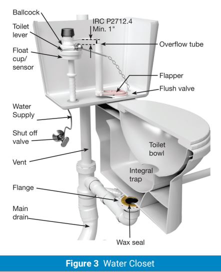
- Toilet tanks (unapproved tank fill valves)
- Sinks and lavatories (unapproved air gap)
- Coffee machines directly connected to the water supply (backflow of coffee into the water supply)
- Soft drink dispensing machines (backflow of carbon dioxide gas (CO2) into copper water supply line)
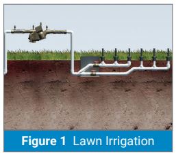
The potable water supply connection to an irrigation system must be protected from contamination by installing an approved/listed backflow prevention device. Atmospheric vacuum breakers (AVB), pressure vacuum breakers (PVB), spill-resistant pressure vacuum breakers (SVB) or a reduced pressure principle backflow preventer (RP) are acceptable assemblies. (See Table 608.1 of the 2021 editions of the IPC or Table P2902.3 of the 2021 editions of the IRC, depending on the code that is applicable in your area).
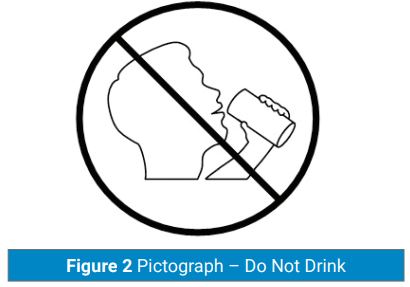
In all buildings with two or more water distribution systems, one potable and the other nonpotable, each system must be identified either by color marking, metal tags or tape and must be consistent throughout the building. Nonpotable water outlets, such as hose connections, open-ended pipes and faucets, shall be identified with signage that reads as follows: “Nonpotable water is utilized for [application name]. CAUTION: NONPOTABLE WATER – DO NOT DRINK.”
In addition to the required wordage, the pictograph shown in Figure 2 shall appear on the required signage. (See Sections 608.8 of the 2021 edition of the IPC and P2901.2 of the 2021 edition of the IRC).
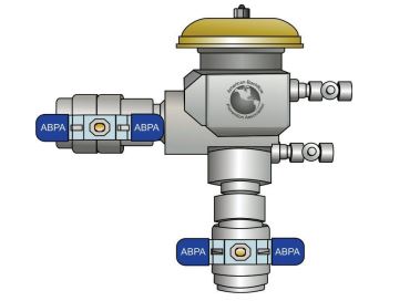
Reduced Pressure Principle Assemblies
- Provide protection against low hazard (pollution) or high hazard (contamination)
- Provide protection against back siphonage and back pressure backflow
- The assembly can be used where it is under continuous pressure from the water supply
- The relief valve opening must discharge through an air gap
- The assembly must be accessible for testing and maintenance
- The assembly cannot be installed below grade where it may be subject to submersion
- Provisions must be made at or near the location of the installation to prevent drainage from the relief valve opening causing damage to the structure when the device is installed in a building or structure
Pressure Vacuum Breakers
- Provide protection against low-hazard (pollutant) or high-hazard (contamination)
- Provide protection against back siphonage only
- Can be used where it is under continuous pressure from the water supply (valving permitted downstream)
- The IPC requires this assembly to have a critical level installation of 6 inches (152 mm) above the flood-level rim. However, the IRC requires the critical level of a pressure vacuum breaker and a spill-resistant vacuum breaker assembly to be set at not less than 12 inches (304 mm) above the highest elevation of downstream piping and the flood-level rim of the fixture or device
- The assembly must be accessible for field testing and maintenance
- Provisions must be made at or near the location of the installation to prevent drainage from the air inlet opening causing damage to the surrounding area when the assembly is installed in a building or structure
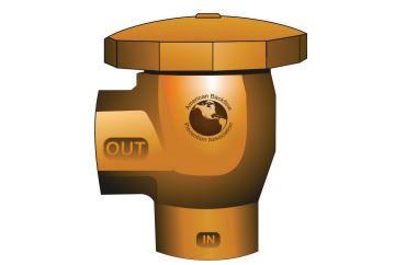
Atmospheric Vacuum Breakers
- Provide protection against low-hazard (pollution) or high-hazard (contamination)
- Provide protection against back siphonage only
- The device cannot be installed where it is under continuous pressure from the water supply (12-hour or less intervals)
- The assembly must be accessible for field inspection and maintenance
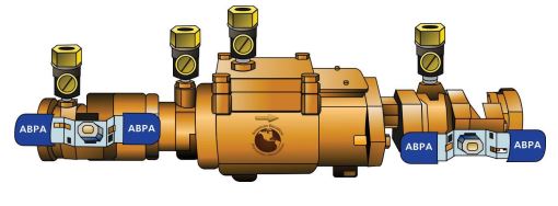
Double Check Backflow Prevention Assemblies
- These assemblies are designed for low-hazard (pollutant) applications subject to backpressure and back siphonage
- The assembly must be accessible for field testing and maintenance
- These assemblies must not be confused with dual check-valve devices or two single check valves placed in series
Automatic sprinkler systems may use a double check fire protection backflow prevention assembly to prevent backflow and detect unauthorized use of water.
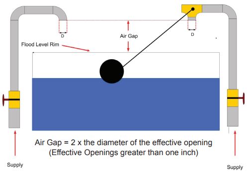
Air Gap Piping System
- The most effective and dependable means of preventing backflow and should be used where feasible
- The minimum required air gap must be measured from the lowest end of a potable water outlet to the flood-level rim of the fixture or receptacle into which such potable water outlet discharges
- Air gaps must comply with Table 608.15.1 of the IPC or P2902.3.1 of the IRC
- The distance between the outlet and a wall or similar obstruction (see Table 608.5.1 of the IPC or P2902.3.1 of the IRC)
Critical Definitions
POLLUTION: An impairment of the quality of the potable water to a degree that does not create a hazard to public health but that does adversely and unreasonably affect the aesthetic qualities of such potable water for domestic use.
CONTAMINATION: An impairment of the quality of the potable water that creates an actual hazard to public health through poisoning or through the spread of disease by sewage, industrial fluids or waste.
Inspection and Testing of Backflow
Backflow prevention assemblies are critical components that protect potable water systems from pollution or contamination sources. The IPC and IRC require annual inspections be made of all backflow prevention assembles to determine whether they are operable. The air gap-like backflow prevention assemblies are critical and must be inspected to determine that proper clearances have been provided. The IPC takes it a step further and requires that inspection of air gaps be part of the annual inspection. Section 312.10.2 of the IPC requires that the test procedure for reduced pressure principle, double check, pressure vacuum, reduced pressure detector fire protection, and spill-resistant vacuum breaker backflow preventer assemblies and hose connection backflow preventers be performed in accordance with one of the following standards: ASSE 5013, ASSE 5015, ASSE 5020, ASSE5047, ASSE 5048, ASSE 5052, ASSE 5056, CSA B64.10 or B64.10.1.
This is an excerpt from the 2021 IPC Code and Commentary. For more information on this publication, visit shop.iccsafe.org
Other Backflow Prevention Related Information
- Access must be provided to backflow preventers as specified by the installation instructions of the approved manufacturer (see Sections 608.14 of the IPC and P2902.6 of the IRC)
- The termination of the piping from the relief port or air gap fitting of a backflow preventer shall discharge to an approved indirect waste receptor or to the outdoors where it will not cause damage or create a nuisance. (See Sections 608.15.2.1 of the IPC and P2902.6.3 of the IRC)
- Proper identification of potable and nonpotable water systems (see Sections 608.8 of the IPC and P2901.2 of the IRC)
For water closet backflow assembly, (see Figure 3).
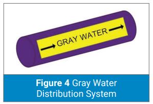
Sections 608.8.2.1 of the 2021 IPC and 2901.2.2.1 of the 2021 IRC require that the color purple be used to identify reclaimed, rain, and gray water distribution systems (see Figure 4).
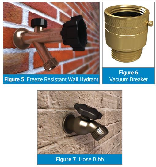
All hose bibbs, wall hydrants, sill cocks and other openings with a hose threaded connection must be protected by an atmospheric vacuum breaker, pressure vacuum breaker, or permanently attached hose connection vacuum breaker (see Section 608.15.4.2 of the IPC or P2902.4.3 of the IRC; also see Figures 5, 6 and 7).
Note: The exceptions are water heater and boiler drain valves and hose bibbs for clothes washing machines.
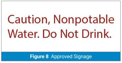
Sections 608.7 of the 2021 IPC and P2903.9.5 of the 2021 IRC allow the installation of freezeproof yard hydrants that drain the riser into the ground if the potable water supply to such hydrants is protected upstream of the hydrants in accordance with Sections 608 of the 2021 IPC and P2902 of the 2021 IRC. The hydrants are to be permanently identified as nonpotable outlets by approved signage that reads as follows: “Caution, Nonpotable Water. Do Not Drink.” (see Figure 8).
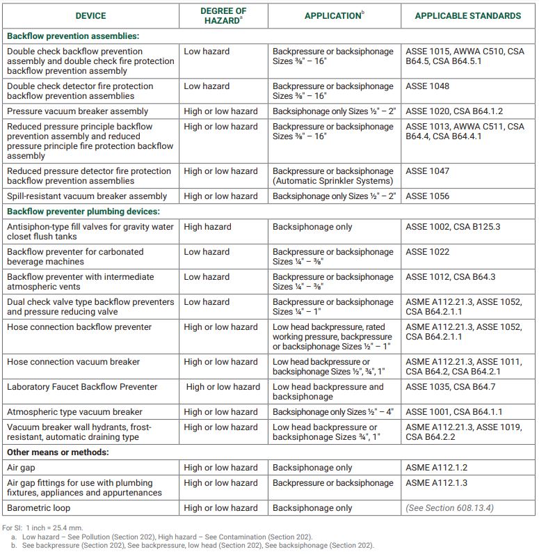
Application For Backflow Preventers
IRC Table 2902.3.1/IPC Table 608.1
