
CodeNotes: Gas Appliance Combustion, Ventilation and Dilution Air Part 2 – Indoor Combustion Air Methods
In part 2 of this CodeNotes series, we will focus on the indoor combustion air methods outlined in the 2021 International Residential Code and International Fuel Gas Code
This edition of CodeNotes — Gas Appliance Combustion, Ventilation and Dilution Air Part 2 – Indoor Combustion Air Methods – is based on the 2021 International Residential Code® and the 2021 International Fuel Gas Code®.
Introduction
Air for combustion, ventilation, and dilution of flue gases for appliances installed in buildings are covered in the International Fuel Gas Code® (IFGC), and for those buildings under the scope of the International Residential Code® (IRC), it is addressed in the (IRC) Chapter 24, “Fuel Gas.” This CodeNotes uses a dual numbering system. The section numbers that appear in parentheses after each (IRC) section number are the section numbers of the corresponding text in the (IFGC).
In Part 1 we learned that there are five methods of supplying combustion air in 2021 (IRC) and 2021 (IFGC). They range from simple (inherently more dependable) methods to more complex methods.
- All outdoor air
- Indoor air
- Combination indoor and outdoor air
- Mechanical combustion air
- Engineered design
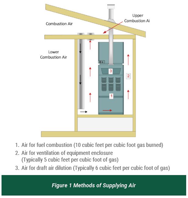
The two methods for supplying combustion air from the outdoors, the traditional method of two direct openings or ducts to the outdoors and a method using one opening or duct to the outdoors were introduced. We learned that combustion air also serves other purposes in addition to supplying oxygen. Combustion air ventilates and cools appliances and the rooms or spaces that enclose them.
Combustion air also plays an important role in producing and controlling drafts in vents and chimneys. Combustion air is the total amount of air provided to the space that contains fuel-burning equipment (see Figure 1).
Indoor Combustion Air
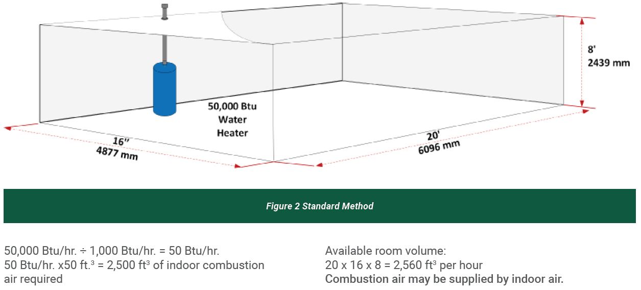
This CodeNotes® will focus on the Indoor Combustion Air methods in Section G2407.5 (304.5). There are two ways to determine the amount of indoor combustion air required from indoors. One is the Standard Method (G2407.5.1) (304.5.1) calculated by a ratio of 50 cubic feet per 1,000 Btu/h (4.8 m3/Kw) of the appliance input rating. However, if the infiltration rate is known to be 0.40 ACH or less, the Known Air Infiltration Rate (KAIR) method G2407.5.2 (304.5.2) must be used. This method is used to calculate the required volume in newer-built buildings with low air infiltration rates.
Standard Method Example
Problem: A 50,000 Btu/hr. water heater with a draft hood is installed in a room 20 feet by 16 feet by 8 feet (see Figure 2). Find the minimum volume of indoor air required.
Recommendation: The Standard Method requires 50 cubic feet per 1,000 Btu/hr. of all appliances in the space to be used to figure the volume. [Ref. G2407.5.1 (304.5.1)]
Known Air-Infiltration-Rate Method (KAIR)
The KAIR Method requires a calculation of the required volume based on two appliance types: fan-assisted and other than fan assisted as shown above. The formula for each appliance type is based on the total combustion air needs of each type of appliance, which differs due to the amount of dilution air required. If installations include both types of appliances, then a separate calculation is done for each type of appliance. These calculations determine the total required air volume. The calculations determine the amount of air for combustion and ventilation required by the appliance for complete combustion. The KAIR method considers the actual or calculated ACH rate and requires the space volumes to be proportionate with the rate. This method can also be used when the ACH RATE is unknown by merely picking a conservative ACH rate (0.40 ACH or less) representing the lowest anticipated ACH rate for the given building. [Ref. G2407.5.2 (304.5.2)]

Example using KAIR Method:

Required Size of Combustion Air Opening
Combining Spaces On The Same Story
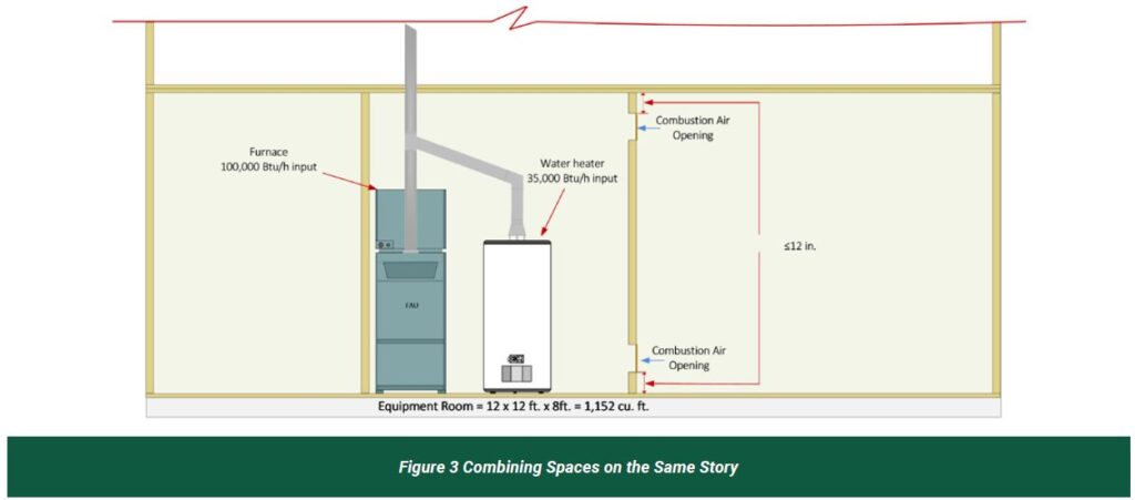
When combining spaces on the same story, each opening shall have a minimum free area of 1 square inch per 1,000 Btu/h (2,200 mm2/Kw) of the total input rating of all appliances in the space, but not less than 100 square inches (0.06 m2). This section also allows drawing combustion air from adjacent spaces (rooms) through two permanent openings. One permanent opening shall commence within 12 inches (305 mm) of the top and one permanent opening shall commence within 12 inches (305 mm) of the bottom of the enclosure. The minimum dimension of air openings shall be not less than 3 inches (76 mm). [Ref. G2407.5.3.1 (304.5.3.1)]
Example (Combining spaces on the same story):
Calculate the required Indoor combustion air volume (135,000 ÷1,000 x 50 = 6,750 cu. ft. volume required > 1,152 cu. Ft.) (see Figure 3).
Combustion air vents will be required.
Next, determine the net free area for each combustion air opening.
The total appliance input = 135,000 Btu/h. 135,000 ÷ 1,000 =135 sq. in. net free area per opening.
Each combustion air opening requires a net free area of 135 sq. in. per opening.
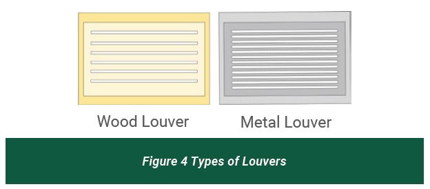
When using louvers or grilles to satisfy combustion air requirements, if known check the manufacture to see what is specified, if unknown, the amount can be calculated as 75% of the gross area for metal louver and 25% of the gross area for wood louvers (Figure 4). Screens shall have a mesh size of at least ¼”. Nonmotorized louvers and grilles shall be fixed in the open position. Motorized dampers or damper blades must be connected to the appliance, preventing appliance operation when the dampers are closed. [Ref G407.10 (304.10)]
In the following example, we are using metal louvers (25% reduction)
Example: 135/0.75 = 180 sq. in.
Note: Use any openings equaling 180 sq. in., such as 12 in. x 15 in.
Combining Spaces In Different Stories
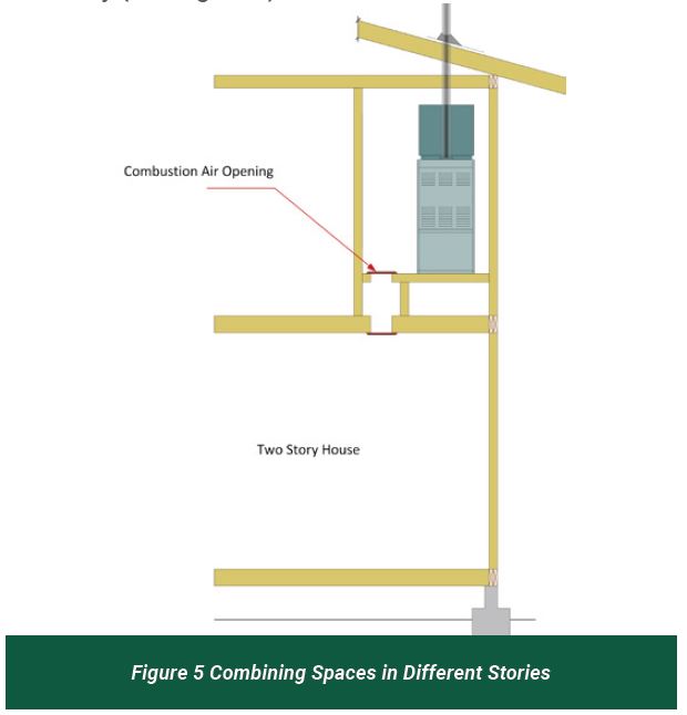
The volume of spaces in different stories shall be considered to be communicating spaces where such spaces are connected by one or more permanent openings in doors or floors having a total minimum free area of 2 square inches per 1,000 Btu/h (4402 mm2/Kw) of total input rating of all appliances. [Ref. G2407.5.3.2 (304.5.3.2)]
This section allows spaces on different floor levels to be combined to increase the available volume for supplying combustion air. A single opening is permitted. The opening or openings can be in a floor or in a door opening to an unenclosed stairway that connects the two stories. This method of combining spaces is particularly useful for dwelling units where the volume of a basement in which the appliances are located can be combined with the open spaces on upper stories by means of louvered doors at the basement stairs. The opening size requirement is the addition of the areas of the two openings required by section [ G2407.5.3.1 (304.5.3.1)]. A combustion air opening in a floor would be considered as a transfer opening in a horizontal assembly (see Figure 5).
Conclusion
The location of fuel-fired appliances is critical for their safe operation and will determine the method of supplying combustion air ranging from simple methods to more complex ones. The compliance with the requirements of the IRC Chapter 24, “Fuel Gas” and the IFGC. must be adhered to in order to ensure good operation. If this is accomplished, a more efficient and safer installation will result.


