
CodeNotes: Installation of Air Admittance Valves
This CodeNotes resource provides information on the correct installation of air admittance valves based on the 2021 International Codes.
This edition of CodeNotes —Installation of Air Admittance Valves — is based on the 2021 International Plumbing Code® and 2021 International Residential Code®.
Introduction

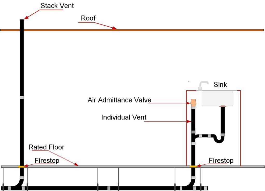
The air admittance valve (AAV) is a device designed to allow air to enter the drainage system to balance the pressure and prevent siphonage of the water trap when negative pressure develops in the system. In this way, it is used on individual vents, branch vents and circuit vents in lieu of terminating vents to the exterior of the structure. Stack vents and vent stacks are permitted to terminate to a stack-type AAV. The exception is for stack vents or vent stacks that serve drainage stacks exceeding six branch intervals.
Because the AAV will not provide relief of positive pressures, there are certain installation requirements specified in the IPC to relieve positive pressure. The one open pipe vent required on every building drainage system in section 918.7 of the IPC and section P3114.7 of the IRC, Vent Required, and section 904.1 of the IPC and section P3102.1 of the IRC, Required Vent Extension, mandates that at least one vent pipe shall extend to the outdoors to relieve the system’s positive pressure. See Figure 1. Section 918.3.1, Horizontal Branches of the IPC, contains measures for pressure relief by requiring the installation of a relief vent where the horizontal branch is located more than four branch intervals from the top of the stack. This would not apply in the IRC.
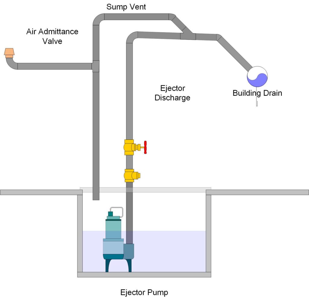
An AAV without an engineered design shall not be utilized to vent sumps or tanks of any type. Figure 2 shows an example of one manufacturer’s engineered design for use of an AAV on a sump.
An AAV has one moving part, a seal, which must be maintained a safe distance above the drain served. In the event of a drain stoppage, the seal may become inoperable or operate improperly if waste is permitted to rise into the AAV assembly.
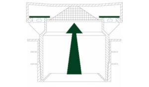
The AAV need not extend above the flood-level rim of the fixture served because in the event of a drain blockage, the device will trap air between it and the rising waste, thereby protecting the device from contamination. The illustration of the AAV in Figure 3 is shown in the closed position. The valve is designed to close and seal under zero or positive pressure.
AAV in Branch Applications (ASSE 1051)
In the IPC, AAVs shall be installed in accordance with the requirements of section 918 and the manufacturer’s instructions. The AAVs shall be installed after the DWV testing required by Section 312.2 or 312.3 has been performed. The IRC requires AAVs be installed in accordance with section P3114 and the manufacturer’s instruction. The AAVs shall be installed after the DWV testing required by Section P2503.5.1 or P2503.5.2 has been performed.
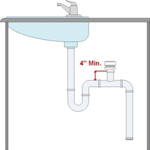
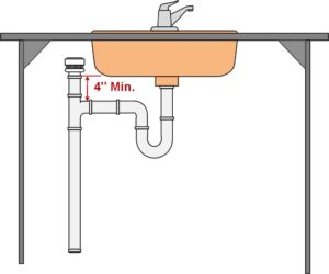
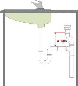
Individual and branch-type AAVs shall not be located not less than 4 inches (102 mm) above the horizontal branch drain or fixture drain being vented. See Figure 4, Examples 1, 2 and 3.
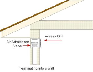
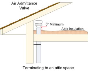
AAVs shall be accessible, should replacement be required. Such valves shall be installed in a location that allows air to enter the valve. Locating the valve in a sink or vanity cabinet is accessible. For in-wall installation, use a recess box/grill combination or access grill. See Figure 5. The AAV shall be installed not less than 6 inches (152 mm) above the insulation material. See Figure 6.
AAV in a Stack Application (ASSE 1050)
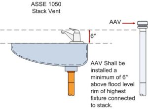
The stack-type AAV shall be located not less than 6 inches (152 mm) above the flood-level rim of the highest fixture being vented. The AAV shall be located within the maximum developed length permitted for the vent. See Figure 7.
AAVs shall be accessible, should replacement be required. Such valves shall be installed in a location that allows air to enter the valve. The AAV shall be installed not less than 6 inches (152 mm) above insulation materials that may block air inlets or otherwise impair the operation of the device.
Plumber Installation Tips
- Always check the manufacturer’s installation instructions for additional recommendations and warranty requirements.
- Most manufacturers recommend that you not install the AAV’s until after the drainage and waste systems have been roughed and tested.
- Teflon tape is usually what manufacturers prefer on the valve thread connection. The use of primer, solvent cement or pipe dope will void most manufacture warranties. Always check the manufacturer’s installation instructions before installing.
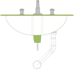
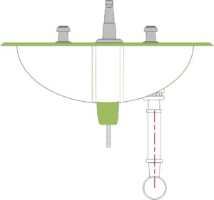
- Pop-up drainage linkage could interfere with the installation of the AAV. Offset drain waste to avoid any conflict. See Figures 8 & 9
In summary, the installation of AAVs must conform to the requirements of section 918 of the IPC, Air Admittance Valves, or section P3113 of the IRC, Vent Pipe Sizing, and the manufacturer’s instruction. Where differences occur between the provisions of the code and the manufacturer instructions, the most restrictive provisions must apply.
To learn more about the code requirements for the installation of AAVs, please refer to the 2021 IPC Code and Commentary, and the 2018 IRC Code and Commentary.


