Methods of venting plumbing fixtures and traps in the 2021 International Plumbing Code
 The International Code Council is proud to distribute a helpful tool — Methods of Venting Plumbing Fixtures and Traps in the 2021 International Plumbing Code: Installation, Flexibility and Opportunity for Savings — to help expand your knowledge of the International Plumbing Code (IPC). The various approaches to venting that are permitted in the 2021 IPC are described in this handy reference tool authored by Lee Clifton, senior director of PMG resources at the Code Council. You will find that these venting provisions offer the installer and designer different paths to achieving an adequately vented system, which could result in cost savings along with ease of installation in different types of construction.
Chapter 9 of the IPC describes a variety of methods to vent plumbing fixtures and traps. The methods have been laboratory tested to determine sizing and installation requirements that provide proper venting to a drainage system. The venting methods have also been field-tested, establishing a long history of satisfactory service.
In this third of a four-part series of articles, we cover three of the remaining six venting methods for which the IPC is probably best known: the common vent, the waste stack vent and wet venting systems. These venting provisions offer the installer and designer different paths to achieving an adequately vented system that could result in cost savings along with ease of installation in different types of construction.
Common vent
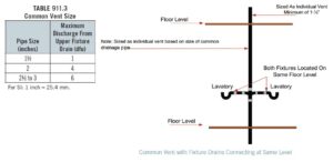
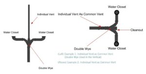
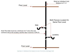
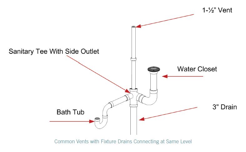
This very simple concept allows two traps to be vented by the same vent. The two traps and their fixture drains can be either at the same level or at different levels, provided that they are on the same floor. The following diagrams show some of the various approaches to common venting. The sizing of common venting is specified in Table 911.3.
 Waste stack vent
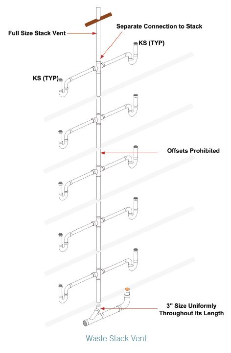
This is a very simple method of allowing a drainage stack to serve as a vent. It greatly extends the concept of a vertical common vent, except for some specific guidelines for installation. For this system to function effectively there cannot be any offsets in the waste stack portion. Once the highest branch interval is connected to the stack, the vent portion may contain offsets, provided such offsets are at least 6 inches above the branch interval connection. The size of the waste stack vent is to be in accordance with Table 913.4.
Note for reference: the size of the stack, which is based on the total branch intervals, shall be maintained the same size from the lowest point of the stack to the vent termination or connection to another approved vent. In other words, if the fixture unit total would require a 3-inch-diameter (76 mm) drain per Table 913.4, then both the stack and its vent must be 3 inches (76 mm) in diameter with no offsets at all until at least 6 inches (152 mm) above the highest branch interval (see diagram).
These two methods of using the drain as a vent, common venting and waste stack venting, are, for the most part, vertical in their application. Now let’s examine Wet Venting. This method is one of the three remaining methods of such venting that are more often found in a horizontal application.
Wet venting
A fixture is said to be wet vented when it serves also to carry the discharge from fixtures connecting into the drainage system at a higher level. The use of wet venting reduces the number of individual vent pipes required by a plumbing drainage system as contrasted with the number required by a conventional system and hence reducing the cost of the venting system. There are many types of venting schemes and methods allowed in the IPC. The Horizontal Wet Venting method located in Section 912.1 of the IPC is one that we will discuss first.
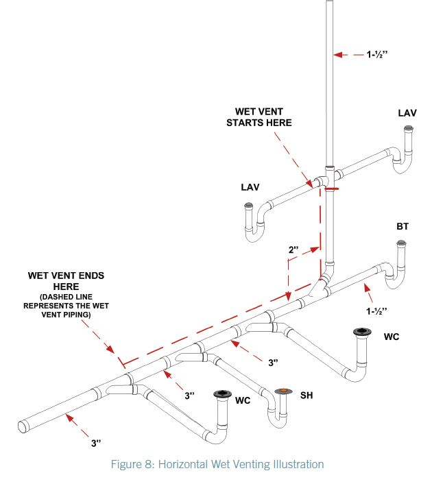 What is a horizontal wet vent? A horizontal wet vent is a horizontal branch drain pipe that has been increased in size larger than what is normally required by Section 710. This increase in pipe size allows for a large air space above the maximum probable waste flow level in the pipe so as to provide for adequate venting airflow in the same pipe as the waste flow. Wet Venting as shown in Figure 8 can be used in both vertical and horizontal applications.
The vertical method may be more common to plumbing installers in certain regions. However, don’t be alarmed by what you see. The horizontal wet venting method is an effective way to provide a safe, sanitary system that can save the contractor and owner time and materials.
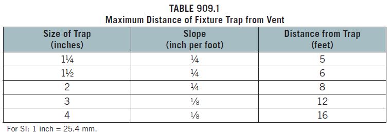
The fixture drain length from the wet vent is limited to the distances shown in Table 909.1. There may be a situation where the fixture location is at a distance that exceeds the maximum trap-to-vent distance. The code allows for any number of individual vented fixtures of the types allowed for a bathroom group to connect to the horizontal wet vent as long the total number of fixtures allowed for the bathroom groups is not exceeded.
Section 202 of Chapter 2 is the key to the maximum number and type of fixtures that can be accommodated by a horizontal wet vent. The definition of Bathroom Group is a group of fixtures consisting of a water closet, lavatory, bathtub or shower, including or excluding a bidet, an emergency floor drain or both. Such fixtures are to be located together on the same floor level. This is done to avoid high flow velocities which could cause excessive turbulence that might block the air space above the waste flow level. Section 912.1 allows any combination of fixtures within two bathroom groups to be vented by a horizontal wet vent. A horizontal wet vent could have as few as two fixtures or as many as ten fixtures but not more than two fixtures of any type can be connected to the system. Each wet vented fixture drain shall connect independently to the horizontal wet vent. This is done to protect the function of each fixture, assuring that one fixture will not influence another’s operation.

The dry vent, the vent that continues upward from the wet vent to the point of termination of connection to another vent, shall be either an individual vent or a common vent for any bathroom group fixture, except an emergency floor drain. Where the dry vent connects to a water closet fixture drain, the drain shall connect horizontally to the horizontal wet vent system. Not more than one wet vented fixture drain shall discharge upstream of the dry vented fixture drain connection. Vertical wet vented systems are required to have the water closets as the most downstream fixture. This is not the case in horizontal wet venting.
The dry vent must be sized in accordance with Section 906.2. Remember, though, that in this case, the drain served is going to be the entire wet vented section. It will need to be at least one-half the diameter of the largest section of pipe in the system. The wet-vented section itself is sized per Table 912.3. Keep in mind that any additional fixtures outside of the wet vent that are to be drained into the same branch must be connected to the branch downstream of the wet vent. Because the wet vent serves as a drain, the type of fittings used must be in accordance with the drainage pattern shown in Table 706.3.
